
Note
Go to the end to download the full example code.
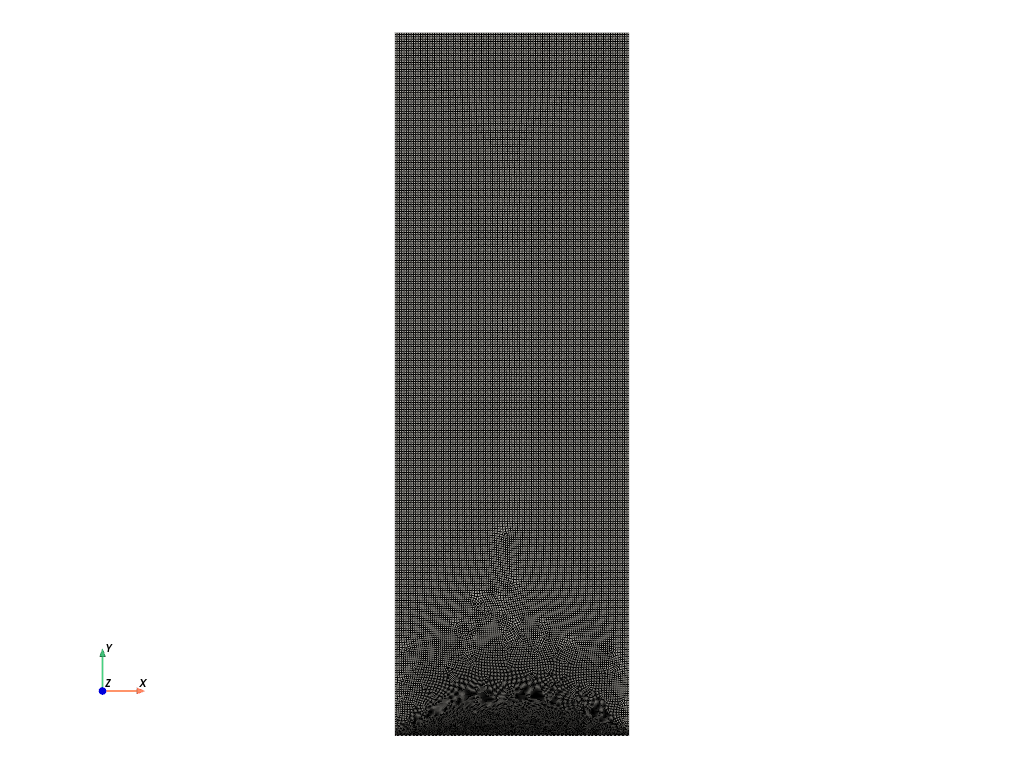
Central Cracked#
This example demonstrates the procedure for generating a mesh for the quarter part of the central cracked specimen used for several simulations.
Below is the .geo file for the central cracked mesh generation.
Reference#
// -----------------------------------------------------------------------------
//
//  Gmsh GEO: Quarter part of a central cracked specimen
//
// -----------------------------------------------------------------------------
//
// gmsh central_cracked.geo  -2 -o central_cracked.msh
//
//   *-------------------------*
//   |                         |
//   |                         |
//   |                         |
//   |                         |
//   |                         |
//   |                         |
//   |                         |
//   |                         |
//   |                         |
//   |                         |
//   |                         |
//   |                         |
//   |                         |
//   *-------------------------*
//

h      = 0.02;  //mesh size
hcrack = 0.002; //mesh size near crack

// ------------------------------------------------------
// ------------------------------------------------------
// A)Geometry Definition: 1)Points
//                        2)Lines
//                        3)Curve
//                        4)Surface

// ------------------------------------------------------
// A1)Points Definitions:
//
//         P4*----------*P3
//           |          |
//           |          |
//         P1*----------*P2
//
//    |Y
//    |
//    ---X
// Z /
//

//           -----Coordinates--
//Points:    -----X,------Y,---Z,
Point(1)   ={   0.0,    0.0,   0,  h};
Point(2)   ={   1.0,    0.0,   0,  h};
Point(3)   ={   1.0,    3.0,   0,  h};
Point(4)   ={   0.0,    3.0,   0,  h};


// ------------------------------------------------------
// A2)Lines Definition
//
//            <-L3
//        *----------*
//     |L4|          |
//        |          | ^L2
//        |          |
//        *----------*
//           L1->
Line(1) = {1, 2};  //L1:from P1 to P2: P1*--L1-->*P2
Line(2) = {2, 3};
Line(3) = {3, 4};
Line(4) = {4, 1};


// -----------------------------------------------------
// A3)Curve Definition
//
//
//        *----<-----*
//        |          |
//        |          |
//        |          ^ Curve 5
//        |          |
//        |          |
//        *----->----*
//

Curve Loop(5) = {1,2,3,4};  //C5: through lines L1,L2,...,L7


// ------------------------------------------------------
// A4)Surface Definition
//
//

Plane Surface(6) = {5};  // Subtract circle loops 39 and 40 from the main surface 5
Recombine Surface {6};


// ------------------------------------------------------
// ------------------------------------------------------
// B)Mesh Generation: 1)Mesh size Box1
//                    2)Mesh size Box2
//                    3)Mesh min(Box1,Box2)
//                    3)Extrude Mesh
//                    4)Mesh Algorithm


// ------------------------------------------------------
// B3) Mesh size Box1
//
Field[7]      =    Box;
Field[7].VIn  = hcrack*10;
Field[7].VOut =  h;

Field[7].XMin =  0.0;
Field[7].XMax =  1.0;
Field[7].YMin =  0.05;
Field[7].YMax =  0.2;

// ------------------------------------------------------
// B3) Mesh size Box2
//
Field[8]      =    Box;
Field[8].VIn  = hcrack;
Field[8].VOut =      h;

Field[8].XMin =  0.0;
Field[8].XMax =  1.0;
Field[8].YMin =  0.0;
Field[8].YMax =  0.01;

// ------------------------------------------------------
// B3) Mesh min(Box1,Box2)
Field[9] = Min;
Field[9].FieldsList = {8};
Background Field = 9;


// ------------------------------------------------------
// B4)Extrude Mesh

//     {X, Y,    Z}    Surface
// Extrude{0, 0,  0.5}{Surface{6}; Layers{{2},{1}}; Recombine;}


// ------------------------------------------------------
// B5)Mesh Algorithm
Geometry.Tolerance = 1e-12;
Mesh.Algorithm = 8;                    // Frontal-Delaunay for quads
Mesh.RecombineAll = 1;                 // Recombine all surfaces
Mesh.SubdivisionAlgorithm = 1;         // All quads subdivision
Mesh.RecombinationAlgorithm = 1;       // Simple recombination

// ------------------------------------------------------
// Physical groups definition
//
Physical Curve("bottom", 7) = {1};
Physical Curve("top", 8) = {3};
Physical Surface("surface", 9) = {6};
Mesh Visualization#
The purpose of this code is to visualize the mesh. The mesh is generated from the .geo file and saved as output_mesh_for_view.vtu. It is then loaded and visualized using PyVista.
import os
import gmsh
import pyvista as pv

folder = "Central_cracked"
Reference#
Initialize Gmsh
gmsh.initialize()
Open the .geo file
geo_file = os.path.join(folder, "central_cracked.geo")
gmsh.open(geo_file)
Generate the mesh (2D example, for 3D use generate(3))
gmsh.model.mesh.generate(2)
Write the mesh to a .vtk file for visualization Note that the input mesh file for the phasefieldx simulation should have the .msh extension. Use “output_mesh_for_view.msh” to generate the mesh for the simulation input. In this case, the mesh is saved in .vtk format to facilitate visualization with PyVista.
vtu_file = os.path.join(folder, "output_mesh_for_view.vtk")
gmsh.write(vtu_file)
Finalize Gmsh
gmsh.finalize()

print(f"Mesh successfully written to {vtu_file}")

pv.start_xvfb()
file_vtu = pv.read(vtu_file)
file_vtu.plot(cpos='xy', color='white', show_edges=True)
Mesh successfully written to Central_cracked/output_mesh_for_view.vtk
Total running time of the script: (0 minutes 6.112 seconds)